Find the modelsim.ini file in the install path, and Change "VoptFlow" parameter to false in the file.
[vsim]
; vopt flow
; Set to turn on automatic optimization of a design.
; Default is on
VoptFlow = 0
    save('./dat/bpnn_00.mat', 'bpnn');
    %    | file name      |  nn obj | // it`s easy.
    newData1 = load('-mat', './dat/bpnn_00.mat');

    % transfer variable format
    vars = fieldnames(newData1);
    for i = 1:length(vars)
        assignin('base', vars{i}, newData1.(vars{i}));
    end
nnResult = sim(bpnn, nnInput); % nnResult is error value
    nnWB = getx(bpnn); % <-- why?
    nnResult = sim(bpnn, nnInput); % nnResult is correct value
void init_timer(void)
{
    TIM_TimeBaseInitTypeDef  TIM_TimeBaseStructure;
    NVIC_InitTypeDef NVIC_InitStructure;

    RCC_APB1PeriphClockCmd(RCC_APB1Periph_TIM2, ENABLE);

    TIM_TimeBaseStructure.TIM_Period = 0xA;     // Counter 12 = 1Mhz = 1us
    TIM_TimeBaseStructure.TIM_Prescaler = 0x5;  // 72Mhz/6 = 12Mhz
    TIM_TimeBaseStructure.TIM_ClockDivision = 0x0;
    TIM_TimeBaseStructure.TIM_CounterMode = TIM_CounterMode_Up;
    TIM_TimeBaseStructure.TIM_RepetitionCounter = 0x0000;
    TIM_TimeBaseInit(TIM2, &TIM_TimeBaseStructure);

    NVIC_PriorityGroupConfig(NVIC_PriorityGroup_0);
    NVIC_InitStructure.NVIC_IRQChannel = TIM2_IRQn;
    NVIC_InitStructure.NVIC_IRQChannelPreemptionPriority = 0;
    NVIC_InitStructure.NVIC_IRQChannelSubPriority = 0;
    NVIC_InitStructure.NVIC_IRQChannelCmd = ENABLE;
    NVIC_Init(&NVIC_InitStructure);

    TIM_ClearFlag(TIM2, TIM_FLAG_Update);
    TIM_ITConfig(TIM2, TIM_IT_Update, ENABLE);
    TIM_Cmd(TIM2, ENABLE);
}
void TIM2_IRQHandler(void)
{
    // Timer2 Interrupt Handler
}


 |
| Altera CycloneIII & Taiwan`s $10 coin |
 |
| The front of the development board |
 |
| The back of the development board |


void TD_Init( void )
{
    CPUCS = 0x12;                       // cpu freq. = 24Mhz
    SYNCDELAY;

    IFCONFIG = 0xA3;                    // ifclk freq. = 30Mhz
    SYNCDELAY;

    PINFLAGSAB = 0x88;   // FLAGA - EP2 EF
    SYNCDELAY;
    PINFLAGSCD = 0xEE;   // FLAGD - EP6 FF
    SYNCDELAY;

    PORTACFG |= 0x80;
    SYNCDELAY;

    FIFOPINPOLAR = 0x3F;                // setting all interface to high active
    SYNCDELAY;

    EP4CFG = 0x02; // Clear Valid
    SYNCDELAY;
    EP8CFG = 0x02; // Clear Valid
    SYNCDELAY;
    EP2CFG = 0xA0;// OUT 512 4x
    SYNCDELAY;
    EP6CFG = 0xE0;// IN  512 4x
    SYNCDELAY;

    // Clear FIFO
    FIFORESET = 0x80;             // activate NAK-ALL to avoid race conditions
    SYNCDELAY;
    FIFORESET = 0x02;             // reset, FIFO 2
    SYNCDELAY;                    //
    FIFORESET = 0x04;             // reset, FIFO 4
    SYNCDELAY;                    //
    FIFORESET = 0x06;             // reset, FIFO 6
    SYNCDELAY;                    //
    FIFORESET = 0x08;             // reset, FIFO 8
    SYNCDELAY;                    //
    FIFORESET = 0x00;             // deactivate NAK-ALL
    SYNCDELAY;

    // OUT EP2
    EP2FIFOCFG = 0x01; // AUTOOUT = 0
    SYNCDELAY;
    OUTPKTEND = 0x82; // 1x
    SYNCDELAY;
    OUTPKTEND = 0x82; // 2x
    SYNCDELAY;
    OUTPKTEND = 0x82; // 3x
    SYNCDELAY;
    OUTPKTEND = 0x82; // 4x
    SYNCDELAY;
    EP2FIFOCFG = 0x11;
    SYNCDELAY;

    // IN EP6
    EP6FIFOCFG = 0x0D;
    SYNCDELAY;
}

typedef struct _lbheader{
    unsigned short identifier;      // 0x0000
    unsigned int filesize;          // 0x0002
    unsigned int reserved;          // 0x0006
    unsigned int bitmap_dataoffset; // 0x000A
    unsigned int bitmap_headersize; // 0x000E
    unsigned int width;             // 0x0012
    unsigned int height;            // 0x0016
    unsigned short planes;          // 0x001A
    unsigned short bits_perpixel;   // 0x001C
    unsigned int compression;       // 0x001E
    unsigned int bitmap_datasize;   // 0x0022
    unsigned int hresolution;       // 0x0026
    unsigned int vresolution;       // 0x002A
    unsigned int usedcolors;        // 0x002E
    unsigned int importantcolors;   // 0x0032
    unsigned int palette;           // 0x0036
} __attribute__((packed,aligned(1))) lbheader;
記住gcc有資料格式對齊的考量,為了到時後讀檔方便,所以加入__attribute__((packed,aligned(1))),強制gcc把結構作緊密排列,這樣是為了到時候讀取資料時可以直接使用指標來擺放資料,就不需要一筆一筆去指定資料。lbheader hbmp; unsigned char* ptr; ptr = (unsigned char *)&hbmp; fread(ptr, sizeof(unsigned char), sizeof(lbheader), fp);像這樣開始讀取檔案的58byte,直接使用unsigned char型態指標從結構開始位址開始寫入,數值就會按照位置擺入結構中。
int readbmp(char* filename, lbheader& hbmp, int mode, unsigned char* buffer)
{
    FILE* ifp;
    char c[128];
    unsigned char* ptr;

    sprintf(c, "./result/%s.bmp", filename);
    ifp = fopen(c, "rb");
    if(ifp==NULL){
        printf("readbmp: file open error\n");
        return -1;
    }

    ptr = (unsigned char *)&hbmp;
    fread(ptr, sizeof(unsigned char), sizeof(lbheader), ifp);

    if(mode==1){
        fread(buffer, sizeof(unsigned char), (hbmp.width*hbmp.height*3), ifp);
    }
    else{
        fclose(ifp);
        return (hbmp.width*hbmp.height*3);
    }

    fclose(ifp);
    return 1;
}
要讀取影像時要先知道影像大小,以便宣告足夠的記憶體空間,所以要呼叫兩次readbmp(),一次先取到header,第二次才真的取影像資料,// 先宣告指標與結構
unsigned char* bimage;
lbheader bmpinfo;
// 取得適當大小的陣列
bimage = (unsigned char *)malloc(sizeof(unsigned char)*readbmp("2", bmpinfo, 0, bimage));
// 讀取影像
readbmp("2", bmpinfo, 1, bimage);
寫入bmp的function。int writebmp(char* filename, lbheader hbmp, unsigned char* buffer)
{
FILE* ofp;
char c[128];
unsigned char* ptr;
sprintf(c, "./result/%s.bmp", filename);
ofp = fopen(c, "wb");
if(ofp==NULL){
printf("writebmp: file open error\n");
return -1;
}
ptr = (unsigned char *)&hbmp;
fwrite(ptr, sizeof(unsigned char), sizeof(lbheader), ofp);
fwrite(buffer, sizeof(unsigned char), (hbmp.width*hbmp.height*3), ofp);
fclose(ofp);
return 1;
}
 |
| DE2-115外盒 |
 |
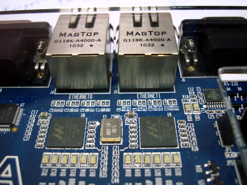
| DE2-115 實驗板 |
 |
| DE2-115 下層內容物 |
 |
| CycloneIV 與記憶體們 |
 |
| GigaByte的Ethernet |
 |
| 電源 |
 |
| 側面 |
 |
| 辛勞的DE2-70 |
#** OpenPPM -- opens and reads a PPM file
#**
proc OpenPPM {} {
    global readimg

    set types { {{PPM Files} {.ppm}} {{All Files} * }}
    set fname [tk_getOpenFile -defaultextension ".ppm" -filetypes $types]
    if {$fname == ""} return
    #::img::current config -file $fname
    $readimg config -file $fname
}
/**
 * Tun-Kai Yao
 * tunkai.yao@gmail.com
 *
 * @ SyntaxHighlighter version
 * 3.0.83 (July 02 2010)
 *
 * @copyright
 * Copyright (C) 2004-2010 Alex Gorbatchev.
 *
 * @license
 * Dual licensed under the MIT and GPL licenses.
 */
;(function()
{
    // CommonJS
    typeof(require) != 'undefined' ? SyntaxHighlighter = require('shCore').SyntaxHighlighter : null;

    function Brush()
    {
        // 字集
        // 資料型態
        var datatypes = 'reg wire ' +
                        'integar unsigned ' +
                        'tri wand triand tri0 tri1 trireg supply0 supply1 ';

        // 基本元件
        var primitives = 'and nand or nor xor xnor ' +
                         'buf not ' +
                         'bufif0 bufif1 notif0 notif1 ' +
                         'pullup pulldown ' +
                         'pmos rpmos nmos rnmos ';

        // 關鍵字
        var keywords =  'module endmodule ' +
                        'input output inout ' +
                        'begin end ' +
                        'parameter defparam ' +
                        'assign deassign always initial genvar ' +
                        'forever repeat disable wait ' +
                        'function endfunction' +
                        'task endtask ' +
                        'generate endgenerate ' +
                        'specify endspecify ' +
                        'posedge negedge ' +
                        'if else for while ' +
                        'case casex casez endcase default ' +
                        //'include timescale ' +
                        //'ifdef endif ' +
                        'celldefine endcelldefine ' +
                        'attribute ' +
                        'specparam  event' +
                        'fork join ';

        // Tasks
        var sysTasks = '$display $monitor $dumpall $dumpfile $dumpflush ' +
                       '$dumplimit $dumpoff $dumpon $dumpvars $fclose ' +
                       '$fdisplay $fopen $finish $fmonitor $fstrobe ' +
                       '$fwrite $fgetc $ungetc $fgets $fscanf $fread ' +
                       '$ftell $fseek $frewind $ferror $fflush $feof ' +
                       '$random $readmemb $readmemh $readmemx $signed ' +
                       '$stime $stop $strobe $time $unsigned $write';

        // 著色
        this.regexList = [
            { regex: SyntaxHighlighter.regexLib.singleLineCComments,    css: 'comments' },              // one line comments
            { regex: SyntaxHighlighter.regexLib.multiLineCComments,     css: 'comments' },              // multiline comments
            { regex: SyntaxHighlighter.regexLib.doubleQuotedString,     css: 'string' },                // strings
            { regex: SyntaxHighlighter.regexLib.singleQuotedString,     css: 'string' },                // strings
            { regex: /\b([\d]+(\.[\d]+)?|0x[a-f0-9]+)\b/gi,             css: 'constants' },             // value
            { regex: /^ *#.*/gm,                                        css: 'preprocessor' },          // #10
            { regex: /^ *`.*/gm,                                        css: 'preprocessor'  },         // `timescale
            { regex: new RegExp("[0-9]+['][bBoOdDhHeEfFtT][0-9a-fA-FzZxX_]+", 'g'), css: 'constants' },
            { regex: new RegExp(this.getKeywords(datatypes), 'gm'),     css: 'color2 bold' },
            { regex: new RegExp(this.getKeywords(primitives), 'gm'),    css: 'color3 bold' },
            { regex: new RegExp(this.getKeywords(sysTasks), 'gm'),      css: 'functions bold' },
            { regex: new RegExp(this.getKeywords(keywords), 'gm'),      css: 'keyword bold' }
            ];
    };

    Brush.prototype = new SyntaxHighlighter.Highlighter();
    // 註冊 verilog 標籤
    Brush.aliases = ['verilog'];
    SyntaxHighlighter.brushes.Verilog = Brush;

    // CommonJS
    typeof(exports) != 'undefined' ? exports.Brush = Brush : null;
})();
/* verilog
 */
`timescale 10/10

module rpa(
    rpa_i_a,
    rpa_i_b,
    rpa_i_ci,
    rpa_o_s,
    rpa_o_co
);

    input  rpa_i_a;
    input  rpa_i_b;
    input  rpa_i_ci;
    output rpa_o_s;
    output rpa_o_co;

    assign {rpa_o_co, rpa_o_s} = rpa_i_a + rpa_i_b + rpa_i_ci;

    //test code
    reg [15:0] testa;
    wire [15:0] testb;
    assign testa = 16'b0;
    assign testb = 16'h0;

    always@(posedge clk or negedge rst)
    begin
        if(!~rst) begin

        end
        else begin

        end
    end


endmodule
5. 文章中插入程式碼的呼叫方式
<pre class="brush: js"> /** * SyntaxHighlighter */ function foo() { if (counter <= 10) return; // it works! }</pre><script type="syntaxhighlighter" class="brush: js"><![CDATA[ /** * SyntaxHighlighter */ function foo() { if (counter <= 10) return; // it works! }]]></script>